Taking A Line For A Walk: Sketching Data
Summer Semester 2012 Elective: Montana State University
with Carson Smuts
MSAAD (M.S. Advanced Architectural Design GSAPP New York) , BArch (UCT Cape Town)

The proliferation of digital design tools has resulted in an increased speed of productivity. With use of rapid prototyping for example, we are able to give over most of our testing, calculations and fabricating to the digital programs and machines available. This allows us to explore many more iterations in design than before. However, much of the potential of those iterations is never explored. We rely so much on the program to make the connections between design iterations for us, that integral opportunities of interjection by the designer are bypassed.
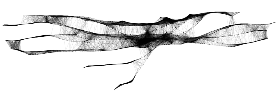
For example, when you draw a line by hand, the line begins a journey. At any given point during that journey, the line might take a sudden change in course, or perhaps it begins to ungulate, negotiating the obstacles in the mind of the architect.
A line drawn by hand could be seen as a processing of data. The data being processed to draw this single line is incredibly complex. It has to take into account the dynamic relationship between the architects mind, the motion of their hand and the feedback through the eye. While the product of a sketch is 2D, we need to view and understand the process of creating a sketch line as 4D. Point,Plane,Space and Time. How can we begin to understand the complexity of such a process?
It is suggested that the retina does the job of 1,000 MIPS (million of instructions per second) in computing. Based on our understanding of the retina, the human brain is said to potentially handle 100 million MIPS. Thats 100,000,000,000,000 Instructions per second! To give us some perspective. An i7 Intel processor today can handle around 0.076 million MIPS (76,000 MIPS). Just a few years ago, in 1999 a Intel Pentium III could handle only 0.002 million MIPS!
With all this powerful technology at our disposal, and given the retina only uses 0.001 million MIPS, how are we drawing our lines today? Surely we are now able to explore the potential of the lines journey in depth. Well, not actually. Even though the processing power has increased exponentially over the years, we still draw our lines using the same calculations from back in the 1990’s. We still implement vectors in our CAD programs to draw lines. A vector consists of a magnitude and direction, made up of two points with an XY value in the cartesian plane or XYZ in 3-Dimensional space.
this is an incredibly simple and diluted process compared a hand drawn line. The user defines two points, by means of an input device such as a mouse, and the computer calculates the line in between. The difference between a hand drawn line and a vector is a difference in the resolution of movement. Its thousands of moves during a drawn lines journey, versus one move of a single vector. Nurbs and Bezier curves are no better, they too take into account a couple control points and interpret the line in between.
These computations for drafting are fine as they allow for accuracy and consistency when fabricating and communicating. However, we are now implement them to design. Effectively sketching inside the digital canvas with vectors, completely forgoing the potential embedded within hand sketch exploration. Hence, the chosen word SKETCH as opposed to DRAWING in the title of this course.
We will be exploring ways to exploit the same number of calculations and the emergent potential of a hand drawn line inside the digital canvas. We will do this through the use of procedural drawing and algorithmic processes, allowing us to journey with the line.
Process Summary
The student will see a fabrication project from inception to completion using Processing, Rhino and Grasshopper. They may utilize any form of rapid prototyping they wish , 3d Printing, Milling, Casting etc.
Project Conceptualization - Interjecting with the Procedural, Parametrically
The students will use Processing in order to develop their own set of tools with which to produce a set of conceptual sketches for a roof, wall or floor modular installation module. It may be one or a set of modules that work together. The purpose of the this is to realize the project from sketch design to product.
The students will have full control and understanding of the digital tools they create from scratch. More importantly, they will be able to explore the potential of any given moment during the creation of a digital sketch. This will empower the student to interject his or her design intent or alteration when ever they wish.
The students digital tool should be able to produce concept sketches in a procedural manner , while at the same time, update and alter interactively in a parametric manner.
To The Point - Under the hood of Parametric engines
Utilizing Grasshopper and Rhino, the project will move into documentation and fabrication during the last 3 weeks of the project. The student sketches will be ported over to Rhino via thousands of points into a parametric array in grasshopper. Then the students will refine these parametric models for fabrication.
The intention of this process is to teach students exactly what a point, curve and surface is in digital terms with regards to how data is read, written and calculated. Introduced into the students work flow is a high level of control over three-dimensional data.